
Recherchez avec le numéro de pièce ainsi que le fabricant ou la description
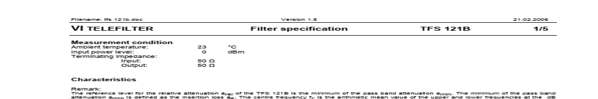
Filename: tfs 121b.doc Version 1.5 21.02.2006 VI TELEFILTER Measurement condition Ambient temperature: Input power level: Terminating impedance: Input: Output: 23 0 50 Ω 50 Ω °C dBm Filter specification TFS 121B 1/5 Characteristics Remark: The reference level for the relative attenuation arel of the TFS 121B is the minimum of the pass band attenuation.
fc.
Data
Insertion loss (reference level) Nominal frequency Passband Pass band ripple Bandwidth 1 3 dB dB arel MHz MHz MHz MHz BW
ae
typ. value
1,25 dB
tolerance / limit
max. 2,5 121,5 fN ± 25 dB MHz kHz dB
fN PB
-
max.
±0,5
2,8
min. MHz
± 25 -
KHz
Relative attenuation fN fN fN fN ± ± ± ± 2,20 3,00 5,00 8,00 MHz MHz MHz MHz … … … … fN fN fN fN ± ± ± ± 3,00 5,00 8,00 20,00
22 35 53 -
dB dB dB
min. min. min. min. max.
5 15 20 40 15
dB dB dB dB dBm
Input power level Operating temperature range Storage temperature range Temperature coefficient of frequency
*) ∆f(Hz) = TCf(ppm/K).
| No. | Partie # | Fabricant | Description | Fiche Technique |
|---|---|---|---|---|
| 1 | TFS121 |

Vectron International |
VI TELEFILTER |

|
| 2 | TFS120 |
Vectron International |
VI TELEFILTER |
|
| 3 | TFS1200 |
Vectron International |
VI TELEFILTER |
|
| 4 | TFS120A |
Vectron International |
VI TELEFILTER |
|
| 5 | TFS120C |
Vectron International |
VI TELEFILTER |
|
| 6 | TFS120E |
Vectron International |
VI TELEFILTER |
|
| 7 | TFS1220 |
Vectron International |
VI TELEFILTER |
|
| 8 | TFS1220B |

ETC |
TELEFILTER |
|
| 9 | TFS1237 |
Vectron International |
VI TELEFILTER |
|
| 10 | TFS124 |
Vectron International |
VI TELEFILTER |
|
| 11 | TFS125A |
Vectron International |
VI TELEFILTER |
|
| 12 | TFS125B |
Vectron International |
VI TELEFILTER |
|