
Recherchez avec le numéro de pièce ainsi que le fabricant ou la description
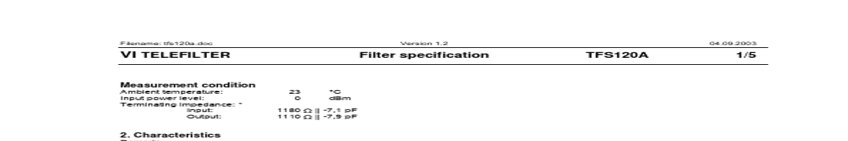
Filename: tfs120a.doc Version 1.2 04.09.2003 VI TELEFILTER Filter specification TFS120A 1/5 Measurement condition Ambient temperature: Input power level: Terminating impedance: * Input: Output: 23 0 1180 1110 °C dBm || -7,1 pF || -7,9 pF 2. Characteristics Remark: Reference level for the relative attenuation a rel of the TFS 120A is the insertion los.
alue
5,6 120 0,6 dB MHz fN dB
tolerance / limit
max. 10,5 120 ± 100 1 kHz dB dB MHz
0,6 35 50 1,8 60
dB dB dB µs ns
max. min. min. max. max.
1 32,5 37,5 3,5 300
dB dB dB µs ns
Group delay Group delay ripple within PB Operating temperature range Storage temperature range Frequency inversion temperature Temperature coefficient of frequency
OTR
35 °C ppm/K²
- 20 °C ... + 85 °C - 20 °C ... + 85 ° C -
TCf
*
*
-0,04
*) The terminating impedances depend on parasitics and q-values of matching elements and the board used, and are to be understood as reference values only. Should there be ad.
| No. | Partie # | Fabricant | Description | Fiche Technique |
|---|---|---|---|---|
| 1 | TFS120 |

Vectron International |
VI TELEFILTER |

|
| 2 | TFS1200 |
Vectron International |
VI TELEFILTER |
|
| 3 | TFS120C |
Vectron International |
VI TELEFILTER |
|
| 4 | TFS120E |
Vectron International |
VI TELEFILTER |
|
| 5 | TFS121 |
Vectron International |
VI TELEFILTER |
|
| 6 | TFS121B |
Vectron International |
VI TELEFILTER |
|
| 7 | TFS1220 |
Vectron International |
VI TELEFILTER |
|
| 8 | TFS1220B |

ETC |
TELEFILTER |
|
| 9 | TFS1237 |
Vectron International |
VI TELEFILTER |
|
| 10 | TFS124 |
Vectron International |
VI TELEFILTER |
|
| 11 | TFS125A |
Vectron International |
VI TELEFILTER |
|
| 12 | TFS125B |
Vectron International |
VI TELEFILTER |
|