
Recherchez avec le numéro de pièce ainsi que le fabricant ou la description
of test circuit and test method) Test Circuit 1 AN17823A 1 + 470µ OUT1 8Ω Vcc 0V 2 3 4 10µ + 5 270k 6 + 7 1.0µ 10k 8 9 68k 5V Stand-by Vin 0V Volume 1.25V Note) If the standby pin is open or 0V, the IC is on standby state. The IC is in the state of volume minimum if the Volume pin is ground. The IC is in the state of volume maximum if the Volume .
lectric Industrial Co., Ltd.
FMSC-PSDA-002-01 Rev.1
Prepared Checked Approved
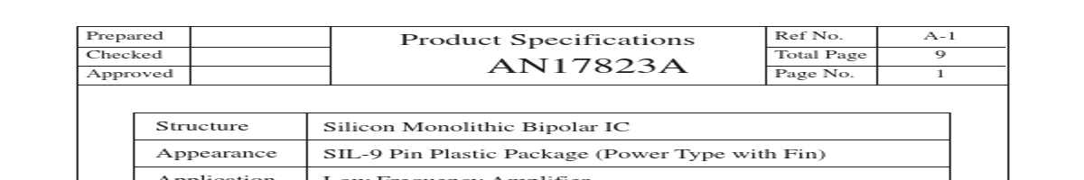
Product Specifications
Ref No. Total Page Page No.
B-1 9 2
AN17823A
B Electrical Characteristics
No Item 1 2 Quiescent Circuit Current Standby Current
(Unless otherwise specified, the ambient temperature is 25°C±2
•C, Vcc=8.0V, frequency=1kHz and RL=8Ω.)
Test Symbol Cir- Conditions cuit ICQ ISTB VNO GV THD PO 1 PO 2 RR Voff Att G Vm 1 1 1 1 1 1 1 1 1 1 1 Vin=0V, Vol=0V Vin=0V, Vol=0V Rg=10kΩ, Vol=0V Po=0.5W, Vol=1.25V Po=0.5W, Vol=1.25V THD=10%, Vol=1.25V Vcc=9V THD=10%, Vol=1.25V Rg=10kΩ, Vol=0V Vr=0.5Vrms, .

…………………..………………………………………………………………………………. 4 Absolute Maximum Ratings ……………………..……………..…………………………......………………… 5 Oper.
| No. | Partie # | Fabricant | Description | Fiche Technique |
|---|---|---|---|---|
| 1 | AN17823 |

UTC |
BTL 4.0W x 1CH POWER AMPLIFIER |

|
| 2 | AN17820A |

Panasonic |
BTL 7.5W X 2-Channel Power Amplifier |
|
| 3 | AN17820B |
Panasonic |
Dual channel BTL 7.5 W audio power amplifier |
|
| 4 | AN17820B |

Matsushita |
LOW-FREQUENCY AMPLIFIER |
|
| 5 | AN17821A |

ETC |
BTL 5.0W x 2ch Power Amplifier |
|
| 6 | AN17821A |
Panasonic |
BTL 5W x 2-Channel Power Amplifier |
|
| 7 | AN17822A |
Panasonic |
LOW-FREQUENCY AMPLIFIER |
|
| 8 | AN17825A |
Panasonic |
A dual channel OTL audio power amplifier |
|
| 9 | AN17803A |
Panasonic |
Audio power amplifier |
|
| 10 | AN17807 |
ETC |
AN17807 |
|
| 11 | AN17807A |
ETC |
AN17807A |
|
| 12 | AN17808A |
Panasonic |
Audio Power Amplifier |
|