
Recherchez avec le numéro de pièce ainsi que le fabricant ou la description
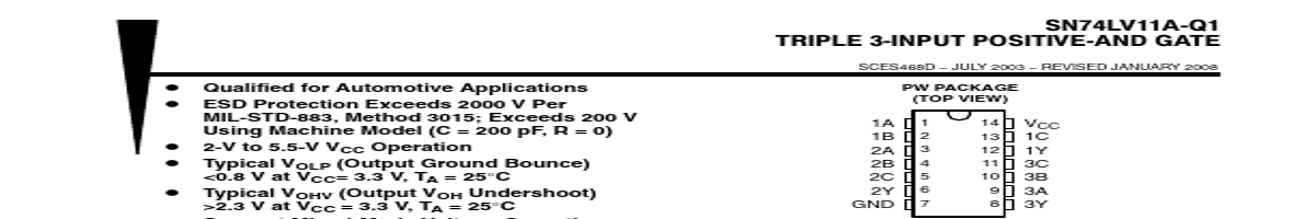
ordering information This triple 3-input positive-AND gate is designed for 2-V to 5.5-V VCC operation. The SN74LV11A performs the Boolean function Y + A • B • C or Y + A ) B ) C in positive logic. This device is fully specified for partial-power-down applications using Ioff. The Ioff circuitry disables the outputs, preventing damaging current backflow throug.
e device when it is powered down. ORDERING INFORMATION† TA PACKAGE‡ ORDERABLE PART NUMBER TOP-SIDE MARKING −40°C to 105°C TSSOP − PW Tape and reel SN74LV11ATPWRQ1 LV11AT † For the most current package and ordering information, see the Package Option Addendum at the end of this document, or see the TI web site at www.ti.com. ‡ Package drawings, thermal data, and symbolization are available at www.ti.com/packaging. FUNCTION TABLE (each gate) INPUTS ABC OUTPUT Y HHH H LXX L XLX L XXL L logic diagram, each gate (positive logic) A B C Y Please be aware that an important notice c.
| No. | Partie # | Fabricant | Description | Fiche Technique |
|---|---|---|---|---|
| 1 | SN74LV11A-EP |

Texas Instruments |
TRIPLE 3-INPUT POSITIVE-AND GATES |

|
| 2 | SN74LV11A |
Texas Instruments |
TRIPLE 3-INPUT POSITIVE-AND GATES |
|
| 3 | SN74LV10A |
Texas Instruments |
Triple 3-Input Positive-NAND Gate |
|
| 4 | SN74LV123A |
Texas Instruments |
Dual Retriggerable Monostable Multivibrators |
|
| 5 | SN74LV123A-EP |
Texas Instruments |
Dual Retriggerable Monostable Multivibrators |
|
| 6 | SN74LV123A-Q1 |
Texas Instruments |
Dual Retriggerable Monostable Multivibrators |
|
| 7 | SN74LV125A |
Texas Instruments |
Quadruple Bus Buffer Gates |
|
| 8 | SN74LV125A-Q1 |
Texas Instruments |
Quadruple Bus Buffer Gates |
|
| 9 | SN74LV125AT |
Texas Instruments |
Quadruple Bus Buffer Gates |
|
| 10 | SN74LV126A |
Texas Instruments |
Quadruple Bus Buffer Gate |
|
| 11 | SN74LV132A |
Texas Instruments |
Quadruple Positive-NAND Gate |
|
| 12 | SN74LV138A |
Texas Instruments |
3-Line to 8-Line Decoders or Demultiplexers |
|