
Recherchez avec le numéro de pièce ainsi que le fabricant ou la description
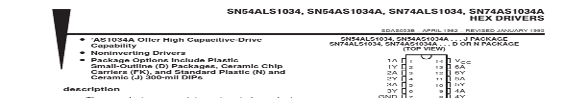
These devices contain six independent noninverting drivers. They perform the Boolean function Y = A. The SN54ALS1034 and SN54AS1034A are characterized for operation over the full military temperature range of − 55°C to 125°C. The SN74ALS1034 and SN74AS1034A are characterized for operation from 0°C to 70°C. FUNCTION TABLE (each buffer) INPUT OUTPUT A Y H.
8 6Y NC 5 17 NC 2Y 6 16 5A NC 7 15 NC 3A 8 14 5Y 9 10 11 12 13 4A NC − No internal connection logic symbol† logic diagram (positive logic) 1 1A 3 2A 5 3A 9 4A 11 5A 13 6A 2 1Y 4 2Y 6 3Y 8 4Y 10 5Y 12 6Y † This symbol is in accordance with ANSI/IEEE Std 91-1984 and IEC Publication 617-12. Pin numbers shown are for the D, J, and N packages. 1 1A 3 2A 5 3A 9 4A 11 5A 2 1Y 4 2Y 6 3Y 8 4Y 10 5Y 13 6A 12 6Y PRODUCTION DATA information is current as of publication date. Products conform to specifications per the terms of Texas Instruments standard warranty. Production processing .
| No. | Partie # | Fabricant | Description | Fiche Technique |
|---|---|---|---|---|
| 1 | SN74ALS1035 |

Texas Instruments |
HEX NONINVERTING BUFFERS |

|
| 2 | SN74ALS1035D |
Texas Instruments |
HEX NONINVERTING BUFFERS |
|
| 3 | SN74ALS1035N |
Texas Instruments |
HEX NONINVERTING BUFFERS |
|
| 4 | SN74ALS1002A |
Texas Instruments |
Quadruple 2-Input Positive-NOR Buffer |
|
| 5 | SN74ALS1004 |
Texas Instruments |
HEX INVERTING Deiver |
|
| 6 | SN74ALS1005 |
Texas Instruments |
Hex Inverting Buffer |
|
| 7 | SN74ALS109A |
Texas Instruments |
Dual J-K Positive-Edge-Triggered Flip-Flop |
|
| 8 | SN74ALS10A |
Texas Instruments |
Triple 3-Input Positive-NAND Gate |
|
| 9 | SN74ALS112A |
Texas Instruments |
Dual J-K Negative-Edge-Triggered Flip-Flop |
|
| 10 | SN74ALS11A |
Texas Instruments |
TRIPLE 3-INPUT POSITIVE-AND GATE |
|
| 11 | SN74ALS1245A |
Texas Instruments |
OCTAL BUS TRANSCEIVER |
|
| 12 | SN74ALS133 |
Texas Instruments |
13-INPUT POSITIVE-NAND GATE |
|