
Recherchez avec le numéro de pièce ainsi que le fabricant ou la description
• Operating range: 2 V to 5.5 V • Maximum tpd of 6.5 ns at 5 V • Low power consumption: maximum ICC of 10 μA • ±8-mA output drive at 5 V • Schmitt trigger action at all inputs makes the circuit tolerant for slower input rise and fall time • Latch-up performance exceeds 250 mA per JESD 17 2 Applications • Enable or disable a digital signal • Controlling an i.
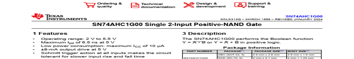
3 Description
• Operating range: 2 V to 5.5 V
• Maximum tpd of 6.5 ns at 5 V
• Low power consumption: maximum ICC of 10 μA
• ±8-mA output drive at 5 V
• Schmitt trigger action at all inputs makes the circuit
tolerant for slower input rise and fall time
• Latch-up performance exceeds 250 mA per JESD
17
2 Applications
• Enable or disable a digital signal
• Controlling an indicator LED
• Translation between communication modules and
system controllers
1 A
2 B
The SN74AHC1G00 performs the Boolean function Y = A
• B or Y = A + B in positive logic.
PART NUMBER SN74AHC1G00
Package Information
P.
| No. | Partie # | Fabricant | Description | Fiche Technique |
|---|---|---|---|---|
| 1 | SN74AHC1G00-Q1 |

Texas Instruments |
Positive-NAND Gate |

|
| 2 | SN74AHC1G02 |
Texas Instruments |
Positive-NOR Gate |
|
| 3 | SN74AHC1G02-EP |
Texas Instruments |
Positive-NOR Gate |
|
| 4 | SN74AHC1G04 |
Texas Instruments |
Single Inverter Gate |
|
| 5 | SN74AHC1G04-Q1 |
Texas Instruments |
Automotive Single Inverter Gate |
|
| 6 | SN74AHC1G08 |
Texas Instruments |
Single 2-Input Positive-AND Gate |
|
| 7 | SN74AHC1G08-Q1 |
Texas Instruments |
Automotive Single 2-Input Positive-AND Gate |
|
| 8 | SN74AHC1G09 |
Texas Instruments |
Positive-AND Gate |
|
| 9 | SN74AHC1G125 |
Texas Instruments |
Single Bus Buffer Gate |
|
| 10 | SN74AHC1G126 |
Texas Instruments |
Single Bus Buffer Gate |
|
| 11 | SN74AHC1G126-EP |
Texas Instruments |
Single Bus Buffer Gate |
|
| 12 | SN74AHC1G14 |
Texas Instruments |
Single Schmitt-Trigger Inverter Gate |
|