
Recherchez avec le numéro de pièce ainsi que le fabricant ou la description
of the boot-strap circuit construction, please contact Mitsubishi Electric C4 C3 Protection circuit (UV) Protection circuit (UV) (Note 6) DIP-IPM Inrush current limiter circuit Drive circuit Drive circuit Drive circuit P AC line input H-side IGBTS (Note 4) U V W M AC line output C Z Fig. 3 N1 VNC N CIN Drive circuit L-side IGBTS Z : ZNR (Sur.
3)
• Fault signaling : Corresponding to a SC fault (Low-side IGBT) or a UV fault (Low-side supply).
• Input interface : 5V line CMOS/TTL compatible, Schmitt Trigger receiver circuit.
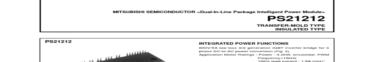
APPLICATION AC100V~200V three-phase inverter drive for small power (0.2 kW) motor control.
Fig. 1 PACKAGE OUTLINES
2.8
1 2
3 4
5 6
7
8
9 10 11 12 13
14 15 16 17 18 19 20 21
11.5
31
2-φ4.5
22 23 24 25 26
10
10
10 67 79
20
13.4
21.4
3.8
TERMINALS CODE 1. UP 4. VUFS 2. VP1 5. VP 3. VUFB 6. VP1
7. VVFB 8. VVFS 9. WP
10. VP1 13. VWFS 16. CIN 19. UN 11. VPC 14. VN1 17. CFO 20. VN 12. VWFB 15. VNC 18.
| No. | Partie # | Fabricant | Description | Fiche Technique |
|---|---|---|---|---|
| 1 | PS21204 |

Mitsubishi Electric Semiconductor |
Dual-In-Line Package Intelligent Power-Module |

|
| 2 | PS21205 |
Mitsubishi Electric Semiconductor |
Dual-In-Line Package Intelligent Power-Module |
|
| 3 | PS21244-E |

Powerex Power |
Intellimod Module Dual-In-Line Intelligent Power-Module |
|
| 4 | PS21245-E |
Powerex Power |
Intellimod Module Dual-In-Line Intelligent Power-Module |
|
| 5 | PS21246-E |
Powerex Power |
Intellimod Module Dual-In-Line Intelligent Power-Module |
|
| 6 | PS21254-E |
Powerex Power |
Intellimod Module Dual-In-Line Intelligent Power-Module |
|
| 7 | PS21255-E |
Powerex Power |
Intellimod Module Dual-In-Line Intelligent Power-Module |
|
| 8 | PS21255-EP |
Powerex Power |
Dual-In-Line Intelligent Power Module |
|
| 9 | PS21265-AP |

Powerex |
Dual-In-Line Intelligent Power Module |
|
| 10 | PS21265-AP |

Mitsubishi |
Dual-In-Line Package Intelligent Power Module |
|
| 11 | PS21265-P |
Powerex |
Dual-In-Line Intelligent Power Module |
|
| 12 | PS21265-P |
Mitsubishi |
Dual-In-Line Package Intelligent Power Module |
|