
Recherchez avec le numéro de pièce ainsi que le fabricant ou la description
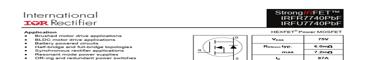
Application Brushed motor drive applications BLDC motor drive applications Battery powered circuits Half-bridge and full-bridge topologies Synchronous rectifier applications Resonant mode power supplies OR-ing and redundant power switches DC/DC and AC/DC converters DC/AC inverters G Benefits Improved gate, avalanche and dyna.
125°C 5 TJ = 25°C 0 0 5 10 15 20 VGS, Gate -to -Source Voltage (V) Fig 1. Typical On-Resistance vs. Gate Voltage 1 www.irf.com © 2014 International Rectifier 100 80 60 40 20 0 25 50 75 100 125 150 TC , Case Temperature (°C) 175 Fig 2. Maximum Drain Current vs. Case Temperature Submit Datasheet Feedback November 5, 2014 IRFR/U7740PbF Absolute Maximum Rating Symbol Parameter ID @ TC = 25°C Continuous Drain Current, VGS @ 10V (Silicon Limited) ID @ TC = 100°C Continuous Drain Current, VGS @ 10V (Silicon Limited) IDM Pulsed Drain Current PD @TC = 25°C Maximum Power Dissipat.
| No. | Partie # | Fabricant | Description | Fiche Technique |
|---|---|---|---|---|
| 1 | IRFU7740 |

INCHANGE |
N-Channel MOSFET |

|
| 2 | IRFU7746 |
INCHANGE |
N-Channel MOSFET |
|
| 3 | IRFU7746PbF |

International Rectifier |
Power MOSFET |
|
| 4 | IRFU7440 |
INCHANGE |
N-Channel MOSFET |
|
| 5 | IRFU7440PbF |
International Rectifier |
HEXFET Power MOSFET |
|
| 6 | IRFU7440PbF |

Infineon |
power MOSFET |
|
| 7 | IRFU7540PbF |
International Rectifier |
Power MOSFET |
|
| 8 | IRFU7546PbF |
International Rectifier |
Power MOSFET |
|
| 9 | IRFU010 |
International Rectifier |
Transistor |
|
| 10 | IRFU012 |
International Rectifier |
Transistor |
|
| 11 | IRFU014 |
INCHANGE |
N-Channel MOSFET |
|
| 12 | IRFU014 |
International Rectifier |
Power MOSFET |
|